Differential Mobility Particle Sizer (DMPS)
Introduction
Differential mobility particle sizing is an alternative to the optical sizing technique described here [link] for measurement of submicron aerosol size distributions. Optical techniques are limited in being unable to detect particles smaller than 50-100nm, and are also susceptible to sizing errors resulting from variations in particle shape and refractive index. Differential mobility techniques are able to measure much smaller particles, down to 2.5nm and are not sensitive to differences in refractive index, but are not able to achieve the same temporal resolution as optical instruments, and are also sensitive to variations in particle shape.
The Differential Mobility Particle Sizer (DMPS) couples a differential mobility analyzer, which classifies charged particles according to their mobility in an electric field, and a condensation particle counter (CPC) to count particles of a specific mobility. Other instruments using variations on this technique include the SMPS and HTDMA. The centre for atmospheric science has two DMPS systems which were built in house, capable of producing aerosol size distributions covering the size range of 2.5-900nm every 10 minutes. The size range and time resolution can be configured as required for specific applications. More details of the general technique and our implementation of it are given below.
Differential Mobility Analyzer
When a charged particle suspended in a gaseous medium is placed in an electric field, the particle experiences a force which is dependant on its charge and the strength of the electric field. This force causes the particle to accelerate along the field lines. This acceleration is opposed by viscous forces within the fluid, which are dependant on particle size and fluid viscosity, and which increase with increasing particle velocity. Thus a particle reaches its terminal velocity when electrical and viscous forces are balanced.
Electrical mobility is described by the following equation, which is derived from Stokes’ law.
Zp= n e Cc / 3 π η Dp
where Zp = Electrical mobility, n = Number of charges on the particle, e = Elementary charge, Cc = Cunningham slip correction, η = Dynamic viscosity of air and Dp = Radius of particle.
The Cunningham slip correction accounts for the discrete nature of the dynamic viscosity due to the particle being bombarded by individual air molecules. This factor becomes increasingly important for smaller particles, but is relevant over the whole size range measured by DMA systems.
The Cunningham slip correction factor is given by the following equation:
Where C is the correction factor, l is the mean free path, d is the particle diameter, An are experimentally determined coefficients which for air are: A1 = 1.257, A2 = 0.400, A3 = 0.55
Thus electrical mobility is dependant mainly on charge and particle size, with less significant dependancies on temperature and pressure as these affect the viscosity of air. For a given charge, smaller particles are more mobile than larger ones.
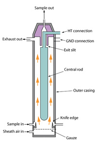
The differential mobility analyzer classifies particles according to their electrical mobility. As can be seen in the diagram, the DMA consists of a cylinder, the walls of which are earthed, with a charged central rod, thus setting up an electric field in the space between the walls and the rod. The main flow through the DMA is particle free 'sheath' air. The particle flow is injected at the outside edge of the DMA, particles move towards the central rod at a velocity determined by their electrical mobility. At the far end of the central rod is a slit through which particles of a given mobility may exit, while all other particles exit with the exhaust flow, or are deposited on the central rod. The mobility of particles which exit through the slit is determined by the DMA geometry (distance between the wall and central rod and effective length), the sheath flow rate, and the electrical field strength. In order for the DMA to work correctly, all flows must be laminar. In practice in order to scan an aerosol size distribution the voltage applied to the central rod is varied with time, either smoothly or in discrete steps. The size range which can be scanned by a single DMA is limited by the voltage which can be applied (too high a voltage causes the insulating properties of air to break down and arcing to occur) and the accuracy with which it can be controlled. Within certain limits the size range to be scanned can be adjusted by changing the sheath flow rate; however the typical dynamic range for a single DMA is about 1:30.
In the atmosphere most aerosol are charged, often with multiple elementary charges, in order for classification by electrical mobility to be meaningful in terms of particle size, the aerosol must be given a known charge distribution. This is done by exposing the particles to a stream of beta radiation, resulting in a charge distribution known as a Fuchs distribution. This distribution has known fractions of the aerosol population which are singly, doubly and triply charged etc. When viewing the output from a DMA set to select a single electrical mobility with an optical particle counter, multiply charged peaks can clearly be seen. Clearly when performing a scan, the presence of multiply charged particles has the potential to affect the results. This is generally dealt with by physically limiting the maximum particle size which may enter the DMA (this is usually done with an impactor) to just above the maximum size which is to be scanned. Thus there can be no multiply charged particles present in the largest size bins. In turn multiply charged particles may be removed from smaller size bins based on the known charge distribution and the measured number concentration of these larger particles.
In addition to the multiple charging issues, the output of a DMA is also not completely monodisperse for several other reasons, including particle diffusion and turbulence. The actual output from a DMA set at a particular electrical mobility is actually a narrow distribution of mobilities peaking at the desired mobility. This distribution is referred to as the transfer function of the DMA, and must be carefully measured to obtain accurate particle number concentrations from DMA scans.
For spherical particles mobility diameter is equivalent to volumetric diameter, however for non spherical particles this is not the case. For such particles mobility diameter is a function of particle shape and orientation, as it is the cross sectional area perpendicular to the direction of particle motion which determines the drag on the particle and hence electrical mobility. Additionally the electric field within the DMA may cause certain types of non spherical particle to align with the field. If particles align such that their minimum cross section is perpendicular to the direction of motion, their mobility diameter will be less than their volume equivalent diameter. For aggregate particles which have a fractal nature, the mobility diameter may be significantly larger than the volume equivalent diameter of the material present.
The Centre for Atmospheric Science DMPS Systems
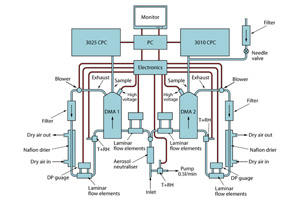
In order to obtain the measurement size range of 2.5-900nm, our DMPS systems are composed of two DMAs and CPCs operating in parallel. The two DMA’s having different geometries and hence different size ranges. Typically sizes in the range 2.5 – 35nm are measured using a short DMA, and sizes 20nm upwards measured using a long DMA. Both DMAs are of the Vienna design. The size distribution is built up by stepping the voltage applied to the central rod in logarithmically spaced discrete steps. A TSI model 3025 CPC in high flow mode (inlet flow of 1.5 lpm) is used on the outlet of the short DMA, and a TSI model 3010 CPC (inlet flow of 1.0 lpm) is used on the outlet of the long DMA. Both DMAs are operated with a sheath to aerosol flow ratio of 10:1. However with a 10lpm sheath flow and a maximum voltage of 12,000V on the central rod the largest size which can be selected with the long DMA is only about 450nm. To get to larger sizes, a lower sheath flow rate is used, typically between 5 and 7 lpm. In order to maintain the 10:1 ratio and provide the inlet flow required by the CPC, a small particle free bleed in flow is added between the outlet of the DMA and the inlet of the CPC.
In order to provide accurate size and number concentration data it is important that all flows through the DMAs are carefully monitored and controlled. Sheath flows are provided by a closed loop re-circulating system monitored using a calibrated laminar flow element flow meter. The signal from this flow meter is used by the PID controller to control the speed of the rotary blower and set the required flow. Aerosol flows are set by the CPC and in the case of the long DMA a combination of the CPC and bleed system. Aerosol flows are also monitored with laminar flow element meters.
Aerosol particles are sensitive to changes in temperature and relative humidity. Condensed water present on such particles exists in equilibrium with the gas phase under sub saturated conditions, so particle size changes in response to changes in humidity. The diameter of a soluble particle at 90%RH may be double that at 20%RH, while an insoluble particle is much less sensitive. Additionally other species such as nitrate are particularly sensitive to changes in temperature. In general temperatures within the DMPS instrument are different than ambient temperatures (may be warmer or cooler depending on prevailing conditions), thus affecting relative humidity. Most of our DMPS measurements are made on dry aerosol thus allowing comparisons to be made between multiple sites without the influence of variations in temperature and humidity. In order to measure dry, the sheath flow path includes a Perma-pure membrane drier, with a very dry <5%RH counterflow. This maintains the sheath flow at around 10-15%RH, which is low enough for all soluble particles to be measured in their dry crystalline form. The aerosol flow is rapidly dried by vapour diffusion when it comes into contact with the dry sheath in the DMA. Temperature and humidity of all flows are also recorded. In some circumstances it is desirable to measure the actual ambient size distribution. In this case, the humidity of the counterflow air passing through the driers is adjusted such that the humidity of the sheath flow matches the ambient humidity.
Like other instruments it is necessary for DMPS systems to be calibrated against known standards. In the case of the DMPS system, a number of calibrations are carried out. Laminar flow elements are calibrated using a bubble flow calibrator. DMA sizing is carried out using certified calibration particles. Latex or polystyrene spheres dispersed from solution using a PMS nebuliser are used to calibrate the long DMA, and gold spheres dispersed from solution using a TSI electro spray generator are used to calibrate the short DMA. Additionally the transfer function of each DMA is also measured using a broad aerosol distribution.
Click here to see information on projects where the DMPS systems have been used.
The two portable DMPS instruments are partially supported by the NCAS Facility for Ground-based Atmospheric Measurement (FGAM.