Airborne Droplet Analyser
General Information
The Airborne Droplet Analyser measures cloud droplet diameter and velocity simultaneously, and is capable of measuring droplets in the size range of 0.5 - 200 microns with a better than 0.5 micron resolution, and velocities (along the axis of the probe) ranging from zero to several hundred meters per second (positive or negative). While it is designed for aircraft use, the instrument is also able to operate in a ground based setting, with or without aspiration, though at low wind speed the data rate is rather low. The Airborne Droplet Analyser is able to cope with very high data rates, corresponding to particle concentrations of several thousand per cc, can distinguish between spherical and non spherical particles (ie. between water and ice particles), and is not limited in it's resolution by the ambiguities of Mie theory. Hence it represents a major advance over the previous generation of cloud droplet sizing probes such as the Forward Scattering Spectrometer Probe. The Airborne Droplet Analyser is manufactured and distributed by TSI inc.
Principle of Operation
The ADA is based on the principles of Laser Doppler Velocimetry (LDV) and Phase Doppler Particle Analysis (PDPA), which are well established and documented techniques for measurement of fluid velocity (LDV) and particle diameter (PDPA) in a lab setting. The ADA is the first instrument to extend this technique to the field/airborne setting.
In the basic LDV technique, light from a single laser beam is split into two beam of equal intensity, one of which has a frequency shift applied to it. These two beams are directed into the flow, such that they intersect. At the point of intersection the beams interfere, and a moving interference pattern is set up (moving because of the frequency shift applied to one of the beams). This point where the beams intersect defines the sample area of the instrument. When a particle passes through the point of intersection some light of varying intensity is scattered into the detector. The frequency of the intensity variation is directly related to the frequency difference between the two beams, and the velocity of the particle accross the interference pattern. With the frequency shift between the two beams, the system is able to measure reverse flows. Addition of second and third pairs of beams of different frequencies allows the measurement of the second and third component of the flow velocity.
PDPA may be viewed as an extension of the LDV technique. A PDPA system uses multiple detectors at different collection angles. Data from the first detector is used for standard LDV, while the phase difference in the signals between pairs of detectors is proportional to the particle diameter. No calibration is needed for this technique as the phase difference is totally dependant on the laser wavelength and the optical configuration. Unlike other optical sizing methods scattered intensity is not used to deduce the size of the particle. Generally two pairs of detectors with different angular separation are used to give two independant measurements of the particle diameter. With correctly chosen angles one pair will provide a course unambiguous measurement of size (ie. no more than 180o phase shift over the entire size range). While the other pair will give a fine, but ambiguous measurement of size (ie. phase shift will wrap past 180o several times over the size range of the instrument). By combining the measurement from both pairs of detectors, a fine unambiguous measurement is obtained. Also since the measurements are actually of the local radius of curvature at different points on the surface of the droplet a measure of the sphericity can be obtained, allowing discrimination between water and ice particles.
System Details
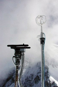
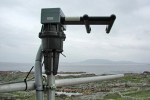
The Airborne Droplet Analyser is very similar to a standard TSI 1d PDPA system, with fiber optic probes. The probe itself being the unique component to ADA. The ADA probe is constructed so that transmitter and receiver optics are housed in a single sealed, heated aerodynamic enclosure suitable for mounting externally on an aircraft. All optical components are fixed, reducing the need for optical alignment of the head, and setting the system to operate using refraction at the 30o forward scattering angle. The probe head is connected to the laser and beam splitter system using two monomodal fibers on the transmission side, and the receiving optics are connected using multimodal fiber to three separate photodetectors housed in the data unit. The head can be located up to about 20m away from the laser and signal processing units. The optical signals are converted to electrical signals by the photodetector module, which are then passed to a custom high speed digital signal processor for analysis, before the resultant data is passed to a high spec PC for final analysis, display and storage. The ground based ADA system at UMIST uses a 100mW Argon Ion laser and operates on the 514nm line (typical output power at the probe head 5mW per beam), and uses a frequency shift of 40MHz (common to all TSI systems) on the shifted beam.
Data Validation and Processing
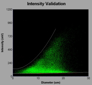
The ADA system records data for individual particles, and for each particles stores a set of parameters including doppler frequency, phase shifts, scattered intensity, burst duration, and arrival time. This allows data validation to be carried out on a particle by particle basis, and as raw data is stored for each particle this can be repeated after the event with different criterior applied. The main validation method is intensity validation. Simply the intensity of light scattered by a droplet through a given collection angle is related to droplet size (this is the basis of many optical sizing instruments). Hence for a known size particle, a maximum expected intensity can be derived. Particles passing through the edges of the beam are less intensely illuminated and hence scatter less light than the maximum. The intensity validation algorithm defines an acceptable range of intensities for a given droplet size, data points whose intensities fall outside this envelope are rejected. Intensity validation allows an almost size independant sample area to be defined, by rejecting particles which pass through the very edges of the beam. (It should be noted that the beams have a gaussian intensity distribution, and small particles passing through the edges will not scatter enough light to trigger the detection system, however a much larger particle passing through the same region of the beam would scatter enough light to be detected and so the sample area would be size dependant). Intensity validation also allows the rejection of spurious data points caused for example by coincidence of multiple drops in the sample area, reflected light, or multiple scattering, which fall a long way from the intensity envelope.
In addition to intensity validation, a probe sample volume correction is applied to correct for any size dependant sample area effects. The magnitude of which is highly dependant on the intensity validation applied.
Current Areas of Work
The Airborne Droplet Analyser has been used with some success in a number of field projects so far (see link below), to study both cloud droplets and super-micron aerosol. Some results from one such project are also given. As ADA is a very new instrument, and uses a completly different technique to existing droplet sizing instruments, an important part of the work being done is comparing ADA with this previous generation of probes under a variety of conditions. Including field trials (such as during CLACE2) and lab intercomparisons under controlled conditions. Hopefully this will allow differences in performance to be identified and understood, and to enable comparison of new and old data sets. The example data shows and illustration of the type of differences currently observed between ADA and FSSP data.
Other work currently being undertaken arises from the fact that ADA is an adaptation from standard lab instrumentation, but when used in the field is being used in a completely different manner than in the lab. For example lab use of a PDPA system would often comprise of setting up experimental apparatus (eg a spray nozzle) making measurements for a short period, then repeating with different settings. This requires a somewhat different software system from that required to make continuous measurements in the field for a period of several days or weeks. While TSI have provided a custom version of the software that goes part-way to meeting our requirements, work is ongoing to develop data tools that will allow efficient analysis of the large quantities of data collected.
Field use also is rather more demanding on the hardware than lab use, and unexpected problems such as solar interference with the laser power meter, and photo-detector module still present some difficulties. While these issues do not prevent the collection of data, inability to use the laser power meter in ambient light conditions makes monitoring of the beam power more difficult (ie have to physically block the window before measurement can be made), and light getting into the photodetectors causes spurious data points (generally fairly easy to reject) and scattered intensities which also have a component related to ambient light level and probe orientation (makes intensity validation more difficult to apply). Several potential solutions are being considered, including software and hardware options. For example on the hardware front construction of an inlet (which could be aspirated to improve the data rate under low wind speed conditions) to shade the probe windows is one possible solution.
Further software work will look at extending the lower range of ADA size measurements to slightly smaller particles, which are currently being detected by the system. However at present they are not sized properly as the phase shift wraps passed 180o, so they are sized as very large, and rejected by intensity validation due to their very small intensity.
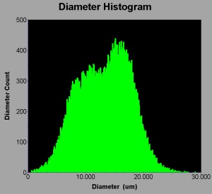
Some sample ADA data from a recent project
ADA Project Involvement
Publications using ADA data
The ADA Instrument is supported by the NCAS Facility for Ground-based Atmospheric Measurement (FGAM).