ACTIVE Project-Egrett Measurements
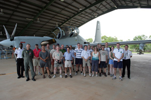
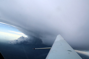
The Egrett aircraft was equipped with instrumentation to characterise anvil outflow from the convective systems being studied, including thermal, aerosol, gas phase and cloud microphysical properties. More details of the measurements made, instruments used and the groups involved are given below. The Egrett was operated according to two general flight plans, depending on the specific objectives of the day’s flying. When flown in conjunction with other aircraft studying specific convective systems, especially those of an isolated nature, the Egrett flew multiple legs through the anvil produced by the storm. These were flown at a variety of levels and at different distances from the convective storm. Legs were also flown along the length of the anvil. Between each leg the Egrett spent some time in clear air, so that differences between the anvil and the surrounding air could be established. On other days the Egrett was flown on surveys, both out to sea, and inland to establish a general climatology of air in the region.
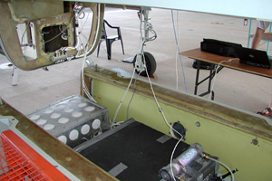
The Egrett only has a small cabin, with very little space for instrumentation, so the majority of the instrumentation and data systems were located in various unpressurised parts of the aircraft, including fuselage bays, a removable u-bay, landing gear bays, and wing pylons. Two u-bays were available which were fitted with a different set of instrumentation, allowing instruments flown to be easily swapped between flights. In addition to the standard instrument fits, for a few flights, an experimental ozone lidar was flown. In order for this to be flown, all the cloud microphysics instruments, and the instruments from one u-bay had to be removed.
ARA Measurements
ARA made measurements of standard meteorological conditions including 3d winds, temperature and pressure, and recorded aircraft and GPS parameters. Additionally ARA provided logging systems which logged several other instruments installed on the Egrett.
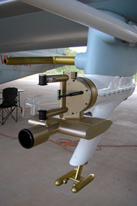
University of Manchester Measurements
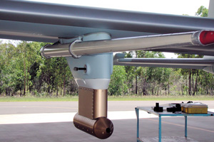
The Centre for Atmospheric Science operated instrumentation to characterise cloud microphysical properties – particle concentration and habit distribution for 10 – 1000µm particles and aerosol properties – number concentration >10nm, number concentration > approx 50nm, size distribution and soot content for particles in the size range 200-700nm. The instruments used for the cloud microphysics measurements were the Cloud Particle Imager (CPI), and Cloud Droplet Probe (CDP). These instruments were mounted on the wing pylons, with a data system in the aircraft cabin, and were operated on all flights with the exception of lidar and transit survey flights. Aerosol concentration measurements were made using two TSI 3010 condensation particle counters, one of which had a set of diffusion disks installed ahead of the inlet to increase its lower cut size. On some flights instead of diffusion disks, the temperature difference between saturator and condenser was adjusted to produce a slightly larger lower cut (around 12nm). Aerosol size distribution and soot content measurements were made with a Single Particle Soot Photometer (SP2). The aerosol instrumentation was all located in the u-bay, with data systems also in the u-bay, or in the case of the CPC’s data was fed to the ARA data systems in the fuselage. The CPC’s were operated on all flights except the transit survey flights, while the SP2 was operated alternately with the NO2 instrument which was installed in the other u-bay. Sample air for the aerosol instruments in the u-bay was provided from a shrouded diffuser inlet similar in design to the CARIBIC inlet located on one of the wing pylons. While this inlet arrangement led to a relatively long internal line length between the instruments and the inlet, it guaranteed that sampled air was unaffected by the aircraft prop wash and engine exhaust.
NCAR Measurements
NCAR provided and operated a DMT Cloud Aerosol and Precipitation Spectrometer (CAPS), which was mounted on the opposite wing pylon to the CPI. CAPS provided measurements of aerosol and cloud particle size distributions in the size range 0.5 – 50 µm, cloud particle size and habit distributions in the size range 25-1550 µm, liquid water content (hot wire probe), temperature, humidity, pressure and true airspeed. CAPS was operated on all flights except the lidar and transit survey flights.
DLR Measurements
DLR made measurements of ozone concentration using a modified version of the Thermo Environ 49C ozone analyser, and frost point temperature (from which relative humidity with respect to ice can be calculated) using a Buck Research CR-2 frost point hygrometer. Located in the fuselage the ozone and frost point measurements were made on all flights except the transit flights.
FZJ Measurements
FZJ made measurements of CO and NOx. CO measurements were made with a custom version of the Aerolaser CO analyser, built to operate in the low temperature and pressure conditions experienced in the Egrett fuselage. NOx measurements were made with a custom built chemiluminescent instrument (reacting O3 with NO) with an inherent sampling time of 10 Hz and a typical detection limit for a 4 s sample of 30-50 pptv. The CO instrument was located in the fuselage, and operated on all flights except the transit flights, while the NOx instrument was located in the second u-bay, and so was alternated with the SP2, and not operated on lidar or transit flights.
University of Cambridge Measurements
The University of Cambridge made measurements of halo-carbon species every five minutes throughout flights using a fully automatic µ-Dirac gas chromatograph instrument. Species measured included CFC-11 (reduced concentrations indicate that stratospheric air is sampled), CH3CCl3, CCl4, CHCl3, Halon-1211 (all industrial tracers), CHBr3, CH2Br2, and CH3I (an excellent tracer marine boundary layer air). Located in the aircraft fuselage, the gas chromatograph was operated on all flights.
University of York Measurements (UK)
Adsorbent tube samples were taken with an automatic tube sampler capable of taking up to 16 samples per flight. These samples were analysed post flight for C4-C9 aliphatics, acetone and monoterpenes which derive from a variety of natural and anthropogenic sources. Located in the aircraft fuselage, the tube sampler was operated on all flights except the transit flights.
York University (Toronto, Canada) Measurements
York University provided an experimental lidar for remote measurements of ozone in anvil outflow, intended to investigate further elevated levels of ozone in anvil outflow which had been observed in previous experiments. Remote measurements removed the possibility of several aircraft or inlet related artefacts which may occur with in-situe ozone measurements under these conditions. Additionally York University operated two water vapour tuneable diode laser (TDL) instruments, one of which was a special open flow path instrument. This was designed to avoid contamination of water vapour measurements by ice accumulated on the air inlet. These TDL’s were operated on all flights.